Along with grinding equipment Mid-West Machine™ designs and manufactures various types of peripheral handling equipment to work in conjunction with its grinders. Mid-West Machine™ has set the standard of the industry for decades and will continue to do so for future decades.
Outstanding features of Mid-West Machine™ Traveling Grinders
- Specifically designed for ease of maintenance and operation, Mid-West Machine™ grinders feature outstanding visibility of the work area from the environmentally controlled operators cab.
- Control levers for the operation of the grinder’s functions are located in the armrests of the completely cushioned industrial quality, fully adjustable seat. A “touch screen” HMI and data terminal monitors and controls all operating sequences. They also provide information and diagnostics for the electrical and hydraulic systems.
- Rigidity of mounting bases – bases are fabricated steel plate, cross braced to reduce twist and stress relived. Component mounting pads are precision machined and keyed/doweled for precise alignment.
- Booms are fabricated steel plate, box construction with internal ribs for stiffness and rigidity. Base of boom is cross keyed to prevent shear loading of the mounting bolts. Boom structure is stress relieved.
- Belt guard along boom is a heavy steel weldment.
- Spindle mounting to boom – machined pilot eliminates shear loading of bolts.
- Automatic belt tensioning provides optimum belt life and rapid grinding wheel change. The drive motor mounts on the sliding motor base plate carried on Nylatron bushings. The bushings slide on chrome plated round bars. It is powered by a hydraulic cylinder to maintain constant tension of the grinding spindle belts.
- The automatic index system provides uniform incremental adjustment of the boom’s outward movement. Index cylinder is fitted with a linear transducer for position control. This allow the choice of manual, single or dual pass indexing and the length of the index. Cylinder mounting pads on base are precision machined to eliminate possibility of bore twist.
- Centralized manual lubrication is provided to all moving parts on the grinder carriage assembly. Individual lines to each bearing are piped to common locations on the grinder assembly. Without this simple system, some bearings/bushings could not be greased on a regular basis.
- Hydraulic drive motors directly coupled to the axles and capable of traversing the grinder at variable speeds from 30 FPM to 200 FPM maximum. Hydraulic drive provides quick reversal response for spot grinding.
- Separate low voltage and high voltage electrical; panels for prevention of arc-flash.
- Low voltage panel is mounted high to allow ease access to the hydraulic pump and motor
- As standard equipment, a bladder-type breather mechanism to provide a sealed reservoir to prevent contamination through the reservoir breather.
- Rigid hydraulic tubing used except at flex points.
- Slow speed drive components mounted on top of main base and easily accessible for maintenance.
Traveling Swarf Booth
- The Swarf Booth travels with the grinder and is driven by two (2) hydraulic motors, supplied from the power unit on the grinder. Swarf booth drive is synchronized with the grinder utilizing a proportional valve to control the drive and a linear transducer to monitor position. Swarf booth basically mirrors the grinder movements.
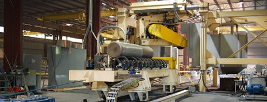
Adjustable Rounds Rotator
- The adjustable rounds rotator consists of a heavy welded steel frame assembly equipped with two (2) line shaft modules, each consisting of (4) four coupled shaft sections, hardened 18" diameter split steel wheels, heavy duty split pillow block bearings. The bearings are mounted on brackets that pivot about a fixed center shaft. This allows for quick adjustment of the rotator wheels center distance. Cylinders are used to raise or lower the line shaft modules. Cylinders have locking valves to prevent movement during grinding.
- Split wheels are mounted with “capture keys” to prevent walking of the wheels on the shafts.
Slab Manipulators
- Slab manipulators are fabricated of heavy steel plates capable of resisting the impacts during slab manipulation. Cylinder rods are protected from direct swarf impact by metal rod covers. All hydraulic hoses are covered with ‘fire sleeve” for protection from hot swarf.
- Hydraulic flow dividers are used to synchronize the arm movements.
Other Mid-West Machine™ products include:
- Stationary Grinders from 200HP to 400HP
- Stationary Gantry Grinders up to 300 HP
- Load/Unload Tables
- End Grinders
Please visit our website for more information on all Mid-West Machine™ equipment or contact us today and get more specifications on how Traveling Grinders could benefit your operation.